| Kaddie Shack, The Kadron Carburetor Specialists |
| How To Rebuild Your Kadron Carburetors |
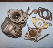
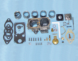
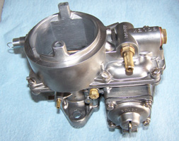
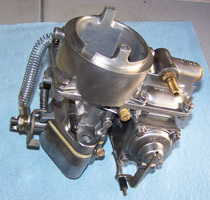
| This is a step-by-step tutorial with basic information on how to rebuild your Kadron carburetors. It does not cover re-bushing, which we'll discuss in another article. We will attempt to run through the whole process that the Kaddie Shack goes through with each and every carburetor that comes through our doors needing service. Some specific information as to procedures that we use is deliberately omitted, such as jetting specifics, how we get the final exterior finish on our rebuilds, how we replace and/or modify certain parts to get better-than-stock performance, and other proprietary information that we have spent countless hours and dollars to obtain. However, for someone who is looking for general and/or very specific information as to how to rebuild their Kaddies, this is the best and most comprehensive article on how to do it. Let's get started: First, and of utmost importance, we start with a general inspection of the carburetor to rebuild. Does it have all exterior visible components? Is it cracked, damaged, or pitted beyond repair? Are the mating surfaces cracked warped between the upper and lower main carburetor housings? Is the accelerator pump housing distorted, cracked or warped? Is the flange between the main body and the insulator plate warped? Are there broken and/or missing screws, and if so, are the threads repairable? Are there "custom" and irreversible modifications that have been installed by previous owners that ruin the integrity of the carburetor? Are the fuel fittings safe and reusable? If all tests are passed, we begin our disassembly. If not, we make sure our "core" carb is repaired and ready for a rebuild, or discarded. |
|
|
|
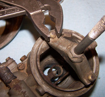
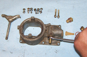
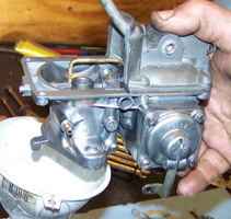
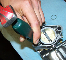
| We start by removing the air cleaner retainer nut, washer, and lid, as well as the air cleaner element itself. Then, we remove the air cleaner base and cork gasket. With the base removed we will find two rounded screw caps that are installed that hold the air cleaner mounting bracket to the carburetor. Many people write us and ask how we get those "rivet things" off. These are not rivets, but rather screws that have a head that breaks off when properly torqued at the manufacturing plant in Brazil, leaving the rounded part shown in the photo. We remove these screws with a special pair of adjustable jaw pliers, and they can be a real bear! After removing the air cleaner and its mounting system, carburetor disassembly begins. We first remove the throttle body from the bottom of the main carburetor, inspect it for the need to re-bush, and set it aside. Before removing, it is necessary to pop the accelerator pump drive rod loose from its driver lever. This is accomplished by gentle prying with a screwdriver. Further disassembly of the throttle body and re-bushing will be covered later. After removing the throttle body, a paper gasket will need to be removed, then an insulator plate (commonly mistakenly referred to as a "spacer"), and then another paper gasket. Discard the gaskets and keep the insulator. |
 |
 |
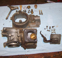 |
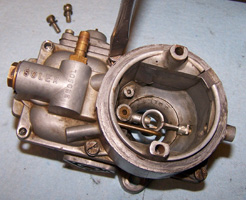
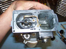
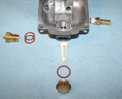
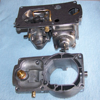
| Now, we flip the carburetor over and remove the upper main housing, or the "lid", by unscrewing the six mounting screws on top of the carburetor. After removing the lid, we take out the needle and seat, the fuel filter access plug and gasket, the fuel filter, and the fuel inlet fitting. We set aside the fuel filter, access plug, and inlet fitting for further cleaning and discard the rest including the original lid screws, as we'll be replacing them with our high-quality stainless steel screws when we get further into the build. We also remove the accelerator pump and spring by taking out the four screws holding it to the side of the main body. |
 |
 |
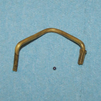 |
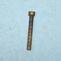
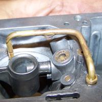
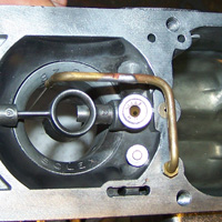
| Next, we remove the float retainer, the float, and its pin. We test each and every float before it leaves, but it's worth mentioning that the older metal floats have a much higher failure rate than do the newer plastic ones. If you have metal floats, you might think about replacing them now. We also check to make sure the floats are properly shaped to ensure they close the needle valve at the appropriate time. We then remove the venturi by loosening the set screw on the side. We also remove the annular discharge booster (the little round thing in the middle of the carburetor throat) and its tensioner spring. Lastly, and of utmost importance, is the need to remove the accelerator pump discharge nozzle. This nozzle can be very difficult to get loose, but it is absolutely necessary to remove it for a successful rebuild. Carefully squeeze the hex-shaped or rounded base, just below the tube itself and pull out. If this is not performed correctly, the carburetor will be ruined. This is the toughest part of the rebuild. Be gentle. If it does not come out, the carburetor housing can be heated with a torch to facilitate easier removal. Once removed, a small ball bearing will be revealed underneath it. Don't lose this ball! It is the secondary check valve, and serves a crucial role in the proper operation of the carburetor. Often, the ball is stuck inside, but they'll come out with lots of air pressure and some TLC. |
| z5 |
 |
 |
 |
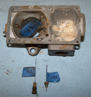
| At this time, we remove the main and idle jets. We carefully measure each main and idle jet with a jet gauge, and make sure that it matches the jetting required for the specific build. Oftentimes we find that the measurements that are stamped on the jets from the factory are not what the actual jet measures, as people often drill them out. Notes are taken and the jets are replaced or re-sized to the match the customer's exact engine requirements at that time. The jets are carefully cleaned if they are the correct size for the application. We also measure the air correction jets, found at the top toward the middle of the carburetor housing. These jets are not replaceable, according to the factory, if they have been modified by a previous owner and are improperly sized. We can, however, replace and/or repair them, but specifics as to how this is accomplished will not be discussed here. The carburetor is now disassembled and ready for a long bath. The carburetors soak in our special cleaning solution for a minimum of 24 hours |
 |
 |
 |
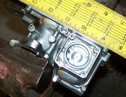
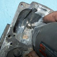
| After removing the disassembled carburetor from the cleaning solution, the passages are each carefully blown out with air. Our special "Kaddie Shack" exclusive cleaning process is completed to the exterior of the carburetor, and Mother's Aluminum Polish is then added to protect the finish. On models equipped for use with an SVDA distributor, the plug is removed from the carburetor housing, a fitting is pressed in, and the vacuum passage carefully modified. A straight edge is used to check for warpage of the mating surfaces, and the carb is resurfaced if needed. The inside of the carburetor is also then cleaned thoroughly. We use a rotary tool to try and get to the hard-to-reach spots that have excessive corrosion, such as the bowl and inside the pump chamber. All small components are then cleaned and polished as needed, double-checked for proper tolerances, and set aside for final assembly. Any parts that are not within our tolerances are either repaired or replaced. The customer's order is then double-checked for accuracy, and the proper venturis are selected, along with the appropriate main and idle jets to properly match engine size, compression, camshaft selection, valve size, port design, vehicle weight, and the altitude where the car will be driven most. |
 |
 |
 |
| The main jet is installed first. Then, the accelerator pump, spring, and diaphragm are secured to the main body, making sure that the metal tab for the diaphragm points away from the carb main housing as it's assembled. At this point, the secondary check valve ball is installed, along with loosely installing the accelerator pump discharge tube. The venturi, annular discharge booster, and its accompanying tensioner spring are also reinstalled. Do not over-tighten the booster either, or it can break, resulting in fire and metal pieces getting sucked into your engine. Now it's time for testing: We use isopropyl alcohol to test the passages of our carbs. First, we test the primary and secondary check valve operation for the accelerator pump. The float bowl is filled with the alcohol solution as the pump is cycled by hand. The stream is observed for the proper amount of flow through the discharge tube and nozzle. The four mating surfaces of the accelerator pump are checked for leaks, which are common. The nozzle is also checked for leaks, which is also common. A leak can spray gasoline into the air filter element, creating a fire hazard. Any cracks in the accelerator pump discharge tube are soldered shut and retested extensively. |
 |
 |
 |
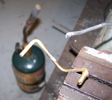
| The discharge nozzle is carefully re-directed to stream the burst of fuel directly in the middle of the butterfly as it opens near the edge of the venturi. It is important that the cracks are repaired after the nozzle is re-directed to prevent the tube from cracking again. We do not secure the nozzle until after the repairs are made, the nozzle is aiming the fuel properly, and the appropriately metered fuel is checked for a proper stream. If the stream is improper, the nozzle may require additional repairs or resizing, or the primary check valve inside the carburetor may require additional repairs or cleaning. The details of these particular repairs are not covered in this article. After making sure the pump circuit is functioning properly, it's time to check the main and idle circuits. We pressurize the fuel chamber by using a special tool we made from an old carb, and check for proper flow through the discharge booster, the idle circuit, and the air correction circuit. A dislodged emulsion tube inside the carburetor can block the flow of fuel, as can other internal failures that are again beyond the scope of this article. If the tests are passed, we stake the pump discharge tube to prevent it from moving, recheck the aim, and cycle one final bowl of alcohol through the pump. We then install the idle jet, the float and its pin, the float retainer, and the main carburetor body gasket. Note the two different types of floats: Metal and plastic. The plastic floats are far more reliable, and a great upgrade if yours are metal. |
 |
 |
 |
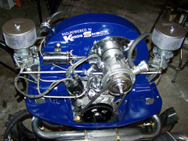
| Once the gasket is in place, we assemble the upper body. First, fuel filter is installed (point side out, this is important, and a mistake often made by inexperience builders!), then the fiber seal, then the filter access plug. The needle valve (needle and seat) is then installed using two copper shims to set it to the correct height. For the main housing gaskets we use, the total thickness of the two shims should be .045" +/- .010". Each manufacturer uses different thicknesses of gaskets, so your requirement may be different. We then install the fuel inlet fitting, using an approved thread sealant to assure gasoline will not leak from the connection. Once the upper and lower housings are ready, they are mated together using six new screws and lock washers. We torque the screws in a circular pattern to initially snug them, then torque them from the inside two out, using a cross-diagonal rotation pattern. A spring is added to one upper mounting screw on this carb, as upgraded dual-cam, heim-equipped linkage will be added for smoother operation. Once assembled and torqued, we double-check the fit of the gasket between the upper and lower main housings. Now... the carburetor is assembled and ready for the previously re-bushed throttle body to be assembled and reinstalled. |
 |
 |
 |
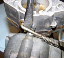
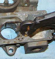
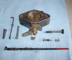
| First, however, the linkage cams must be checked to ensure they are straight, of equal length, and not worn. Otherwise, they will not open at the same time, and synchronizing problems will occur. The idle speed screw and its accompanying cam are also checked for correct geometry and fit. This particular carb has the additional link lever that we use to attach the return spring for the upgraded dual-cam linkage. You'll not that we used a punch to knock out the stock ball and drilled the hole out to 3/16" to attach the linkage. Also note the two different types of idle mixture screws. The early kits had one of these screws to make it easier to get to the passenger's side mixture screw. Once assembled, we install the throttle body back onto the bottom of the assembled carburetor using two special screws, making sure the insulator plate is sandwiched between the carb and throttle body in the proper orientation, with gaskets installed between those. We stake the bottoms of the throttle bodies to prevent the screws from being inadvertently dropped down the intake manifolds when the carbs need service again in the future. Then, we attach the spring from the screw to the spring lever. |
 |
 |
 |
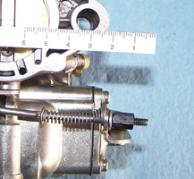
| The pump drive rod is lubed, then inserted into the cam on the side of the butterfly after the spring, washer, shims (as needed) and 7mm adjustment nut are installed. The travel for the fuel pump drive lever is set to a specified measurement, depending on jetting and engine application. Then, the idle mixture screw is installed all the way in, then backed out two full turns; as the idle speed screw is adjusted to where it barely makes contact with its stopper. The carburetor is now sent through a rigorous inspection process (again!), a checklist is filled out by the technician, and it is now ready for delivery. |